QuickPHOTO INDUSTRIAL 4 - Microscope Software
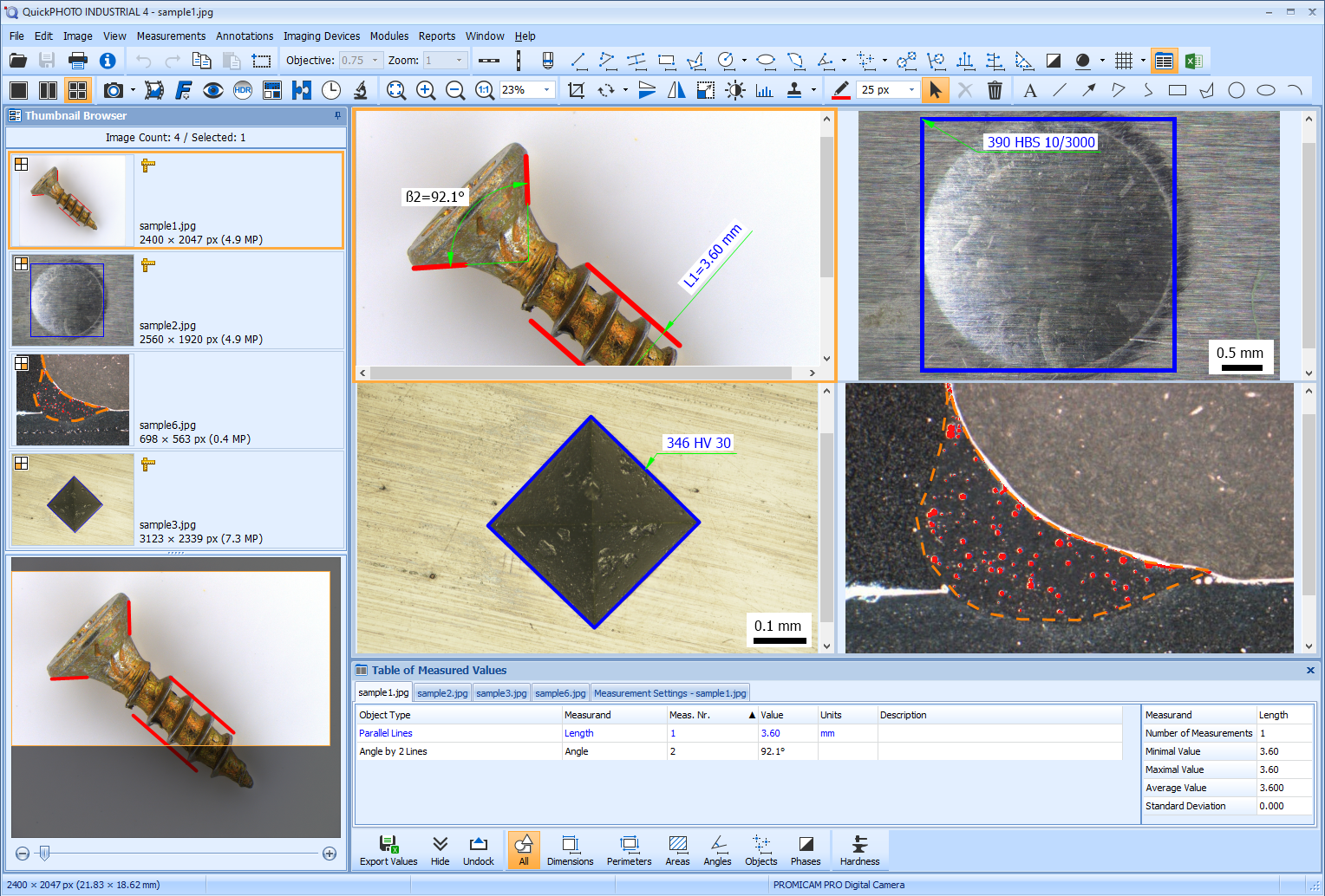
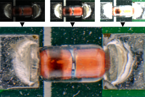
QuickPHOTO INDUSTRIAL 4 represents the most advanced version of the QuickPHOTO microscope software developed by PROMICRA since 2004. It is specifically designed for industrial and material applications. This program includes all the features of QuickPHOTO MICRO 4 version and additionally provides advanced measurement tools for technical applications such as circle and arc measurements, parallel line measurements, hardness testing, weld measurements, phase analysis, and continuous export of measured values directly into an open Microsoft® Excel® workbook.
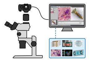
QuickPHOTO INDUSTRIAL 4 is compatible with any brand or type of optical microscope or hardness tester equipped with a photo output, ensuring its universal usability.
What is New in Version 4
You can find an overview of the news on page What is New in QuickPHOTO 4 programs…
Features
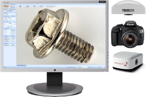
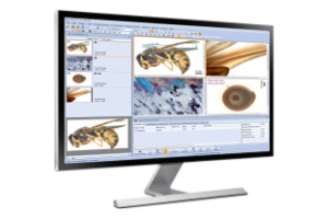
Live View and Image Acquisition
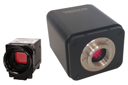
Display live view and capture images from a wide range of imaging devices, including cameras, photo cameras, and scanners.
Annotations and Image Editing
Features for adding text annotations, marking points of interest, and editing images include cropping, rotating to any angle, flipping, resizing, adjusting brightness and contrast, color balance, histogram adjustment, applying filters, and fine-tuning white and black balance.
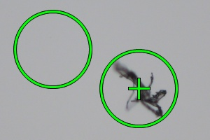
Image Retouching
The clone stamp tool removes specks or debris in images by copying nearby areas.
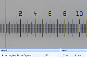
Easy Calibration
Calibration of objectives and zoom magnifications for measurement is simple and intuitive. Calibration data is protected by a digital signature and can be secured with a password for maximum sefety. If an image imported from another program contains a scale, it can be easily calibrated for precise measurements.
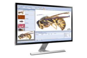
Measurements
Measurements in captured images and live view*. Measured values are displayed in an organized table along with basic statistics.
*Measurements in live view are available only for PROMICAM and Lumenera INFINITY cameras.
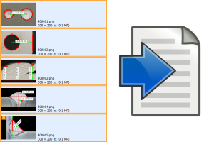
Export of Measured Values
Measured values can be exported as XLSX files for Microsoft® Excel® or as CSV or TXT files for processing in other programs. The export can be performed either as separate files for each image or as a single summary file containing values from selected images.
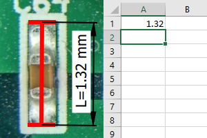
Continuous Export of Measured Values
Measured values can be continuously exported to an open Microsoft® Excel® workbook. This allows measurements to be instantly evaluated using functions or macros set directly within Excel®.
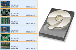
Advanced Image Saving
Advanced features for saving multiple images at once, with the option to automatically save captured images to a predefined folder.
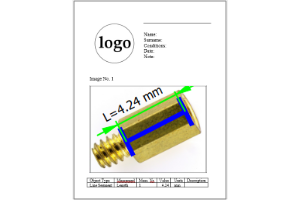
Creating Reports
Images and tables with measured values can be easily exported to reports as DOCX files for Microsoft® Word. Users have the option to create custom report templates with any layout and number of images, tailored to their needs.

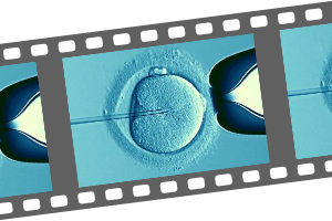
Time-Lapse Image Capturing
Automatic time-lapse imaging with the ability to control computer-controlled illuminators.
Time-Lapse Video
The built-in module for video sequence creation allows you to create video clips from time-lapse images in up to 4K UHD resolution (3840 × 2160 pixels).

Localization
Multilingual, user-friendly interface: English, Czech, German, Slovak, Polish, Spanish, Hungarian, Ukrainian, and Traditional Chinese.
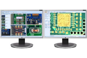
Dual-Monitor Workstations
Dual-monitor workstation support allows the main program window to be displayed on the primary monitor, while the camera control panel with live microscope preview can be placed on the secondary monitor for more convenient operation.
High-Resolution and High-DPI Monitors
The program controls automatically adjust to the DPI value of your monitor. This feature ensures optimal display quality even on high-resolution monitors, including 4K.
Measuring Features
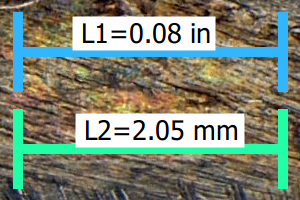
Metric and Imperial Units
Measurement in both metric and imperial units: nm, µm, mm, cm, in, mils, thou. The option to choose the number of displayed decimal places is also available.
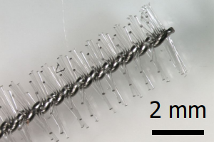
Scale Bar
Insertion of a calibrated scale bar with the option to set the type, size, colors, and orientation (horizontal or vertical).
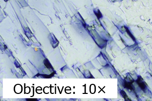
Information About Magnification
Insertion of information about magnification into the image, with the option to adjust the text, size, colors, position, and orientation.
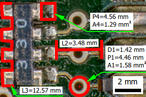
Dimensions
Measurement of dimensions (line segment and polyline)
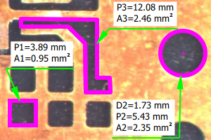
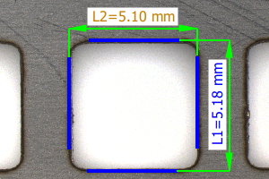
Areas, Perimeters, Radii, and Diameters
- Area and perimeter of a rectangle/square
- Area and perimeter of a polygon
- Area and perimeter of an ellipse
- Radius, diameter, perimeter, and area of a circle
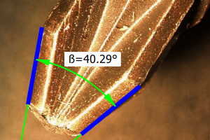
Angles
- Arbitrary angle (defined by three points)
- Angle from the X-axis
- Angle from the Y-axis
- Angle defined by two line segments with the vertex outside the image
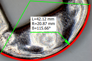
Arc
Measurement of radius, angle, and arc length
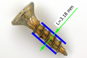
Distance Between Parallel Lines
Measurement of the perpendicular distance between two parallel lines
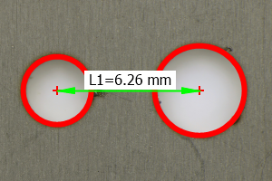
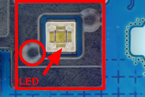
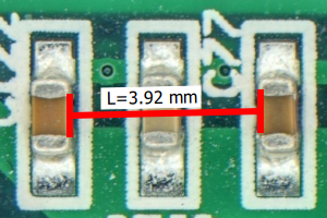
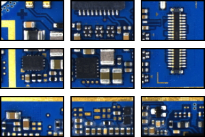
Distance Between Centers of Two Circles
Feature suitable for measuring the distance between the centers of holes in materials, printed circuit boards, and similar objects.
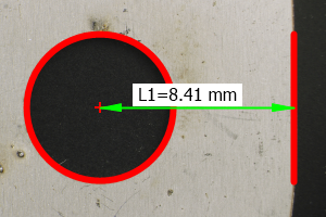
Distance of Circle Center from Line
Feature suitable for measuring the distance from the center of a hole to the edge of a material, printed circuit board, and similar objects.
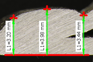
Distance from Reference Line
Feature that allows measuring one or more perpendicular distances from the reference line, suitable for applications such as weld measurements.
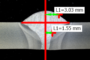
Distance from Axis
Feature that allows measuring one or more perpendicular distances from the axis, suitable for applications such as weld measurements.
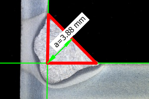
Fillet Weld Thickness
Feature that allows measuring the parameter “a” or “S” of fillet welds.
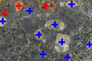
Object Counting
The object counting function allows marking objects with the mouse, with each counted object being marked with a cross. It is easy to count different groups of objects.
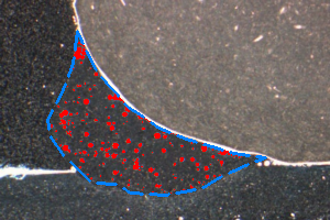
Phase Analysis
Feature for measuring the percentage, area, and number of regions of individual phases in an image, with the ability to define areas of interest, is suitable for material applications such as steel microstructure analysis, composite material analysis, or quality control of welds and castings.
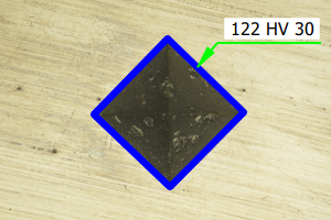
Hardness Testing
Evaluation of Brinell hardness testing (according to the EN ISO 6506-1:2014 and ASTM E10 standards) and Vickers microhardness testing (according to the EN ISO 4516:2002 and ASTM E384 standard).
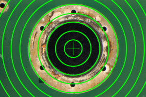
Overlay Grid
Feature for displaying a calibrated rectangular or circular grid with adjustable spacing and position.
Dimensioning of Measurements
Measured values can be freely moved within the image. They are linked to the measured objects using dimensioning, reference, and auxiliary lines in accordance with technical drawing standards. The labeling of measured quantities can be easily adjusted as needed.
Optional Features
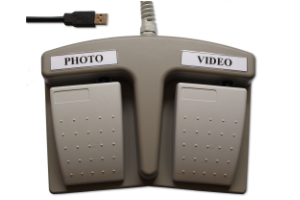
Remote Trigger
A remote trigger is an optional accessory which makes image acquisition even more comfortable. The images can be acquired by pressing a trigger button.
System Requirements
| Minimum Requirements | Recommended Specifications | |
| Processor | Dual-core | Intel® Core™ i5 / AMD Ryzen™ 5 or better |
| Operating Memory | 2 GB | 16 GB or more |
| USB Ports | 2x USB 2.0 / 3.2 Gen 1 | 2x USB 3.2 Gen 1 |
| Display Resolution | 1366 x 768 | 3840 x 2160 (4K) |
| Operating System | Windows® 11 / Windows® 10 Version 22H2 | Windows® 11 |
| In older systems, QuickPHOTO programs in version 3.2 can be used. | ||
| Minimum Requirements | |
| Processor | Dual-core |
| Operating Memory | 2 GB |
| USB Ports | 2x USB 2.0 / 3.2 Gen 1 |
| Display Resolution | 1366 x 768 |
| Operating System | Windows® 11 / Windows® 10 Version 22H2 |
| Recommended Specifications | |
| Processor | Intel® Core™ i5 / AMD Ryzen™ 5 or better |
| Operating Memory | 16 GB or more |
| USB Ports | 2x USB 3.2 Gen 1 |
| Display Resolution | 3840 x 2160 (4K) |
| Operating System | Windows® 11 |
| In older systems, QuickPHOTO programs in version 3.2 can be used. | |
Go to the list of supported devices.
Related Products
Microsoft®, Windows®, Windows Vista®, Excel® are registered trademarks of Microsoft Corp.